
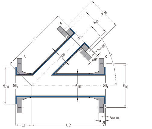
DIN Flanged Lateral Tees 45° (PN 10)
The one-piece design with PFA or PP lining offers a low-resistance flow through the entire component by a streamlined geometry.
Materials:
- carbon steel
- stainless steel
Lining materials:
- PFA (virgin or conductive)
- PP
Flanges according to EN 1092-1
(reading order A-B-C):
- combinations of fixed flanges
- combinations of loose flanges
- combinations of fixed and loose flanges
Other pressure levels:
- PN 16
- PN 25
- PN 40
Special features:
- earthing stud/lug
- vent hole extension
- flange stopper
Optional extras:
- final painting
- non-destructive testing
DN1
| DN2
| L1
(mm) | L2
(mm) | L3
(mm) | d1(1)
(mm) | d4(1)
(mm) | K(1)
(mm) | smin(1)
(mm) | a1(1)
(mm) | a2(1)
(mm) | d1(2)
(mm) | d4(2)
(mm) | K(2)
(mm) | smin(2)
(mm) | a1(2)
(mm) | a2(2)
(mm) | No. of bolts | Wt.
(ca. kg/ | |
DN1 | DN2 | ||||||||||||||||||
25 | 15 | 60 | 160 | 160 | 33.7 | 68 | 85 | 4.0 | 22.0 | 34.0 | 26.9 | 45 | 65 | 4.0 | 20.0 | 30.0 | 4 x M12 | 4 x M12 | 4.2 |
25 | 20 | 60 | 160 | 160 | 33.7 | 68 | 85 | 4.0 | 22.0 | 34.0 | 26.9 | 58 | 75 | 4.0 | 22.0 | 34.0 | 4 x M12 | 4 x M12 | 4.7 |
25 | 25 | 60 | 160 | 160 | 33.7 | 68 | 85 | 4.0 | 22.0 | 34.0 | 33.7 | 68 | 85 | 4.0 | 22.0 | 34.0 | 4 x M12 | 4 x M12 | 5.0 |
32 | 15 | 60 | 200 | 180 | 42.4 | 78 | 100 | 4.0 | 22.0 | 36.0 | 26.9 | 45 | 65 | 4.0 | 20.0 | 30.0 | 4 x M16 | 4 x M12 | 5.8 |
32 | 20 | 60 | 200 | 180 | 42.4 | 78 | 100 | 4.0 | 22.0 | 36.0 | 26.9 | 58 | 75 | 4.0 | 22.0 | 34.0 | 4 x M16 | 4 x M12 | 6.2 |
32 | 25 | 60 | 200 | 180 | 42.4 | 78 | 100 | 4.0 | 22.0 | 36.0 | 33.7 | 68 | 85 | 4.0 | 22.0 | 34.0 | 4 x M16 | 4 x M12 | 6.6 |
32 | 32 | 60 | 200 | 200 | 42.4 | 78 | 100 | 4.0 | 22.0 | 36.0 | 42.4 | 78 | 100 | 4.0 | 22.0 | 36.0 | 4 x M16 | 4 x M16 | 7.6 |
40 | 20 | 90 | 210 | 180 | 48.3 | 88 | 110 | 4.0 | 22.0 | 36.0 | 26.9 | 58 | 75 | 4.0 | 22.0 | 34.0 | 4 x M16 | 4 x M12 | 7.0 |
40 | 25 | 90 | 210 | 180 | 48.3 | 88 | 110 | 4.0 | 22.0 | 36.0 | 33.7 | 68 | 85 | 4.0 | 22.0 | 34.0 | 4 x M16 | 4 x M12 | 7.4 |
40 | 32 | 90 | 210 | 200 | 48.3 | 88 | 110 | 4.0 | 22.0 | 36.0 | 42.4 | 78 | 100 | 4.0 | 22.0 | 36.0 | 4 x M16 | 4 x M16 | 8.3 |
40 | 40 | 90 | 210 | 200 | 48.3 | 88 | 110 | 4.0 | 22.0 | 36.0 | 48.3 | 88 | 110 | 4.0 | 22.0 | 36.0 | 4 x M16 | 4 x M16 | 8.8 |
50 | 25 | 50 | 190 | 190 | 60.3 | 102 | 125 | 4.0 | 22.0 | 40.0 | 33.7 | 68 | 85 | 4.0 | 22.0 | 34.0 | 4 x M16 | 4 x M12 | 8.2 |
50 | 32 | 50 | 190 | 220 | 60.3 | 102 | 125 | 4.0 | 22.0 | 40.0 | 42.4 | 78 | 100 | 4.0 | 22.0 | 36.0 | 4 x M16 | 4 x M16 | 9.2 |
50 | 40 | 50 | 190 | 220 | 60.3 | 102 | 125 | 4.0 | 22.0 | 40.0 | 48.3 | 88 | 110 | 4.0 | 22.0 | 36.0 | 4 x M16 | 4 x M16 | 9.7 |
50 | 50 | 50 | 190 | 230 | 60.3 | 102 | 125 | 4.0 | 22.0 | 40.0 | 60.3 | 102 | 125 | 4.0 | 22.0 | 40.0 | 4 x M16 | 4 x M16 | 10.7 |
65 | 25 | 70 | 280 | 220 | 76.1 | 122 | 145 | 4.0 | 22.0 | 40.0 | 33.7 | 68 | 85 | 4.0 | 22.0 | 34.0 | 8 x M16 | 4 x M12 | 10.3 |
65 | 32 | 70 | 280 | 240 | 76.1 | 122 | 145 | 4.0 | 22.0 | 40.0 | 42.4 | 78 | 100 | 4.0 | 22.0 | 36.0 | 8 x M16 | 4 x M16 | 11.4 |
65 | 40 | 70 | 280 | 240 | 76.1 | 122 | 145 | 4.0 | 22.0 | 40.0 | 48.3 | 88 | 110 | 4.0 | 22.0 | 36.0 | 8 x M16 | 4 x M16 | 11.8 |
65 | 50 | 70 | 280 | 260 | 76.1 | 122 | 145 | 4.0 | 22.0 | 40.0 | 60.3 | 102 | 125 | 4.0 | 22.0 | 40.0 | 8 x M16 | 4 x M16 | 12.9 |
65 | 65 | 70 | 280 | 280 | 76.1 | 122 | 145 | 4.0 | 22.0 | 40.0 | 76.1 | 122 | 145 | 4.0 | 22.0 | 40.0 | 8 x M16 | 8 x M16 | 14.1 |
80 | 25 | 60 | 270 | 230 | 88.9 | 138 | 160 | 4.0 | 24.0 | 40.0 | 33.7 | 68 | 85 | 4.0 | 22.0 | 34.0 | 8 x M16 | 4 x M12 | 12.5 |
80 | 40 | 60 | 270 | 250 | 88.9 | 138 | 160 | 4.0 | 24.0 | 40.0 | 48.3 | 88 | 110 | 4.0 | 22.0 | 36.0 | 8 x M16 | 4 x M16 | 14.0 |
80 | 50 | 60 | 270 | 250 | 88.9 | 138 | 160 | 4.0 | 24.0 | 40.0 | 60.3 | 102 | 125 | 4.0 | 22.0 | 40.0 | 8 x M16 | 4 x M16 | 15.0 |
80 | 65 | 60 | 270 | 270 | 88.9 | 138 | 160 | 4.0 | 24.0 | 40.0 | 76.1 | 122 | 145 | 4.0 | 22.0 | 40.0 | 8 x M16 | 8 x M16 | 16.2 |
80 | 80 | 60 | 270 | 270 | 88.9 | 138 | 160 | 4.0 | 24.0 | 40.0 | 88.9 | 138 | 160 | 4.0 | 24.0 | 40.0 | 8 x M16 | 8 x M16 | 17.3 |
100 | 25 | 115 | 295 | 250 | 114.3 | 158 | 180 | 4.0 | 24.0 | 44.0 | 33.7 | 68 | 85 | 4.0 | 22.0 | 34.0 | 8 x M16 | 4 x M12 | 15.9 |
100 | 50 | 115 | 295 | 270 | 114.3 | 158 | 180 | 4.0 | 24.0 | 44.0 | 60.3 | 102 | 125 | 4.0 | 22.0 | 40.0 | 8 x M16 | 4 x M16 | 18.4 |
100 | 65 | 115 | 295 | 295 | 114.3 | 158 | 180 | 4.0 | 24.0 | 44.0 | 76.1 | 122 | 145 | 4.0 | 22.0 | 40.0 | 8 x M16 | 8 x M16 | 19.6 |
100 | 80 | 115 | 295 | 295 | 114.3 | 158 | 180 | 4.0 | 24.0 | 44.0 | 88.9 | 138 | 160 | 4.0 | 24.0 | 40.0 | 8 x M16 | 8 x M16 | 20.7 |
100 | 100 | 115 | 295 | 295 | 114.3 | 158 | 180 | 4.0 | 24.0 | 44.0 | 114.3 | 158 | 180 | 4.0 | 24.0 | 44.0 | 8 x M16 | 8 x M16 | 22.3 |
DN1 | DN2 | Flanged Lateral Tees 45° (PN 10) | |||||||
fix-fix-fix | fix-fix-loose | fix-loose-fix | loose-fix-fix | fix-loose-loose | loose-loose-fix | loose-fix-Los | loose-loose-loose | ||
25 | 15 |
|
|
|
|
|
|
|
|
25 | 20 |
|
|
|
| - |
|
| - |
25 | 25 |
| - | - |
| - | - | - | - |
32 | 15 |
|
|
|
|
|
|
|
|
32 | 20 |
|
|
|
|
|
|
|
|
32 | 25 |
|
|
|
|
|
|
|
|
32 | 32 |
|
|
|
|
|
|
|
|
40 | 20 |
|
|
|
|
|
|
|
|
40 | 25 |
|
|
|
|
|
|
|
|
40 | 32 |
| - |
|
| - |
|
| - |
40 | 40 |
| - |
|
| - |
| - | - |
50 | 25 |
| - |
|
| - |
| - | - |
50 | 32 |
|
| - | - | - | - | - | - |
50 | 40 |
|
| - | - | - | - | - | - |
50 | 50 |
|
| - | - | - | - | - | - |
65 | 25 |
|
|
|
|
|
|
|
|
65 | 32 |
|
|
|
|
|
|
|
|
65 | 40 |
|
|
|
|
|
|
|
|
65 | 50 |
|
|
|
|
|
|
|
|
65 | 65 |
|
|
|
|
|
|
|
|
80 | 25 |
|
|
|
|
|
|
|
|
80 | 40 |
|
|
|
|
|
|
|
|
80 | 50 |
|
|
|
|
|
|
|
|
80 | 65 |
|
|
| - | - | - | - | - |
80 | 80 |
|
|
| - | - | - | - | - |
100 | 25 |
|
|
|
|
|
|
|
|
100 | 50 |
|
|
|
|
|
|
|
|
100 | 65 |
|
|
|
|
|
|
|
|
100 | 80 |
|
|
|
| - |
|
| - |
100 | 100 |
|
|
|
| - |
|
| - |

Different nominal pipe sizes, total lengths and
other construction types on request.
L = Total length
d1 = Outer diameter of the pipe
d4 = Raised face diameter
K = Bolt circle diameter
smin = Minimum flare thickness
a1 = Minimum length with fixed flange (Type 11) and smin
a2 = Minimum length with loose flange (Types 04/34) and smin
Technical data valid for the pressure level PN 10.
a1 and a2 depend on construction type and lining thickness.
| DN | Lining thickness | Possible vacuum | |||
| standard | thick-walled | 23°C | 150°C | 200°C | |
| 25 | |||||
| 40 | |||||
| 50 | |||||
| 80 | |||||
| 100 | |||||
| = | full vacuum | |
| = | limited vacuum | |
| = | no vacuum | |
| Please refer to the next higher nominal pipe size if your nominal pipe size is not listed. | ||