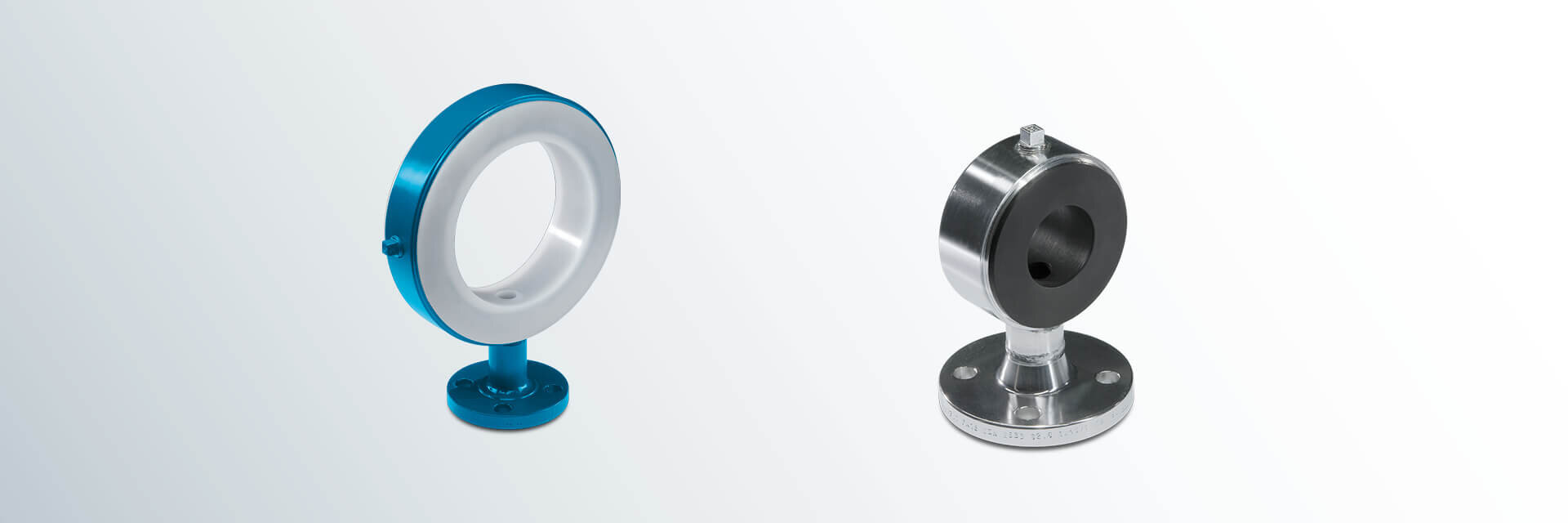
DIN Instrumenten-T-Stücke (PN 10)
Instrumenten-T-Stück oder Messstutzen genannt – die einteilige Lösung mit PFA- oder PP-Auskleidung für den Anschluss Ihrer Meßgeräte. Bei engem Bauraum als kurzes T-Stück verwendbar.
Werkstoffe:
- Normalstahl
- Edelstahl
Auskleidungswerkstoffe:
- PFA (natur oder ableitfähig)
- PP
Weitere Druckstufen:
- PN 16
- PN 25
- PN 40
Anbauten:
- Edungsbolzen /-lasche
- Entlüftungshülse
Extras:
- Decklackierung
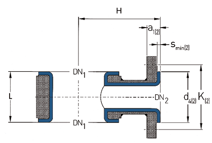
DN1
| DN2
| L
(mm) | H
(mm) | d4(2)
(mm) | K(2)
(mm) | smin(2)
(mm) | a1(2)
(mm) | Schrauben
DN2 | Gewichte
(ca. kg/St.) |
25 | 15 | 50 | 90 | 45 | 65 | 4,0 | 20,0 | 4 x M12 | 2,0 |
25 | 20 | 50 | 90 | 58 | 75 | 4,0 | 22,0 | 4 x M12 | 2,4 |
25 | 25 | 50 | 90 | 68 | 85 | 4,0 | 22,0 | 4 x M12 | 2,6 |
32 | 15 | 50 | 100 | 45 | 65 | 4,0 | 20,0 | 4 x M12 | 2,3 |
32 | 20 | 50 | 100 | 58 | 75 | 4,0 | 22,0 | 4 x M12 | 2,8 |
32 | 25 | 50 | 100 | 68 | 85 | 4,0 | 22,0 | 4 x M12 | 3,0 |
40 | 15 | 50 | 110 | 45 | 65 | 4,0 | 20,0 | 4 x M12 | 2,7 |
40 | 20 | 50 | 110 | 58 | 75 | 4,0 | 22,0 | 4 x M12 | 3,1 |
40 | 25 | 50 | 110 | 68 | 85 | 4,0 | 22,0 | 4 x M12 | 3,3 |
40 | 40 | 75 | 110 | 88 | 110 | 4,0 | 22,0 | 4 x M16 | 5,4 |
50 | 15 | 50 | 115 | 45 | 65 | 4,0 | 20,0 | 4 x M12 | 3,2 |
50 | 20 | 50 | 115 | 58 | 75 | 4,0 | 22,0 | 4 x M12 | 3,7 |
50 | 25 | 50 | 115 | 68 | 85 | 4,0 | 22,0 | 4 x M12 | 3,9 |
50 | 40 | 75 | 115 | 88 | 110 | 4,0 | 22,0 | 4 x M16 | 6,3 |
50 | 50 | 90 | 115 | 102 | 125 | 4,0 | 22,0 | 4 x M16 | 7,6 |
65 | 15 | 50 | 125 | 45 | 65 | 4,0 | 20,0 | 4 x M12 | 4,0 |
65 | 20 | 50 | 125 | 58 | 75 | 4,0 | 22,0 | 4 x M12 | 4,4 |
65 | 25 | 50 | 125 | 68 | 85 | 4,0 | 22,0 | 4 x M12 | 4,6 |
65 | 40 | 75 | 125 | 88 | 110 | 4,0 | 22,0 | 4 x M16 | 8,3 |
65 | 50 | 90 | 125 | 102 | 125 | 4,0 | 22,0 | 4 x M16 | 9,1 |
80 | 15 | 50 | 135 | 45 | 65 | 4,0 | 20,0 | 4 x M12 | 4,5 |
80 | 20 | 50 | 135 | 58 | 75 | 4,0 | 22,0 | 4 x M12 | 5,0 |
80 | 25 | 50 | 135 | 68 | 85 | 4,0 | 22,0 | 4 x M12 | 5,2 |
80 | 40 | 75 | 135 | 88 | 110 | 4,0 | 22,0 | 4 x M16 | 8,3 |
80 | 50 | 90 | 135 | 102 | 125 | 4,0 | 22,0 | 4 x M16 | 11,2 |
100 | 15 | 50 | 150 | 45 | 65 | 4,0 | 20,0 | 4 x M12 | 5,0 |
100 | 20 | 50 | 150 | 58 | 75 | 4,0 | 22,0 | 4 x M12 | 5,4 |
100 | 25 | 50 | 150 | 68 | 85 | 4,0 | 22,0 | 4 x M12 | 5,7 |
100 | 40 | 75 | 150 | 88 | 110 | 4,0 | 22,0 | 4 x M16 | 9,1 |
100 | 50 | 90 | 150 | 102 | 125 | 4,0 | 22,0 | 4 x M16 | 12,2 |
125 | 15 | 50 | 160 | 45 | 65 | 4,0 | 20,0 | 4 x M12 | 6,2 |
125 | 20 | 50 | 160 | 58 | 75 | 4,0 | 22,0 | 4 x M12 | 6,7 |
125 | 25 | 50 | 160 | 68 | 85 | 4,0 | 22,0 | 4 x M12 | 6,9 |
125 | 40 | 75 | 160 | 88 | 110 | 4,0 | 22,0 | 4 x M16 | 11,0 |
125 | 50 | 90 | 160 | 102 | 125 | 4,0 | 22,0 | 4 x M16 | 13,3 |
150 | 15 | 50 | 180 | 45 | 65 | 4,0 | 20,0 | 4 x M12 | 6,9 |
150 | 20 | 50 | 180 | 58 | 75 | 4,0 | 22,0 | 4 x M12 | 7,4 |
150 | 25 | 50 | 180 | 68 | 85 | 4,0 | 22,0 | 4 x M12 | 7,6 |
150 | 40 | 75 | 180 | 88 | 110 | 4,0 | 22,0 | 4 x M16 | 12,1 |
150 | 50 | 90 | 180 | 102 | 125 | 4,0 | 22,0 | 4 x M16 | 14,7 |
200 | 15 | 50 | 210 | 45 | 65 | 4,0 | 20,0 | 4 x M12 | 9,5 |
200 | 20 | 50 | 210 | 58 | 75 | 4,0 | 22,0 | 4 x M12 | 9,9 |
200 | 25 | 50 | 210 | 68 | 85 | 4,0 | 22,0 | 4 x M12 | 10,1 |
200 | 40 | 75 | 210 | 88 | 110 | 4,0 | 22,0 | 4 x M16 | 16,1 |
200 | 50 | 90 | 210 | 102 | 125 | 4,0 | 22,0 | 4 x M16 | 19,6 |
250 | 25 | 50 | 240 | 68 | 85 | 4,0 | 22,0 | 4 x M12 | 13,7 |
250 | 40 | 75 | 240 | 88 | 110 | 4,0 | 22,0 | 4 x M16 | 21,7 |
250 | 50 | 90 | 240 | 102 | 125 | 4,0 | 22,0 | 4 x M16 | 26,4 |
300 | 25 | 90 | 340 | 68 | 85 | 4,0 | 22,0 | 4 x M12 | 27,5 |
300 | 40 | 110 | 340 | 88 | 110 | 4,0 | 22,0 | 4 x M16 | 34,8 |
300 | 50 | 120 | 340 | 102 | 125 | 4,0 | 22,0 | 4 x M16 | 38,5 |
350 | 25 | 90 | 375 | 68 | 85 | 4,0 | 22,0 | 4 x M12 | 43,2 |
350 | 40 | 110 | 375 | 88 | 110 | 4,0 | 22,0 | 4 x M16 | 54,2 |
350 | 50 | 120 | 375 | 102 | 125 | 4,0 | 22,0 | 4 x M16 | 59,7 |
400 | 25 | 90 | 390 | 68 | 85 | 4,0 | 22,0 | 4 x M12 | 48,3 |
400 | 40 | 110 | 390 | 88 | 110 | 4,0 | 22,0 | 4 x M16 | 60,5 |
400 | 50 | 120 | 390 | 102 | 125 | 4,0 | 22,0 | 4 x M16 | 66,6 |
450 | 25 | 90 | 425 | 68 | 85 | 4,0 | 22,0 | 4 x M12 | 51,1 |
450 | 40 | 110 | 425 | 88 | 110 | 4,0 | 22,0 | 4 x M16 | 64,0 |
450 | 50 | 120 | 425 | 102 | 125 | 4,0 | 22,0 | 4 x M16 | 70,6 |
500 | 25 | 90 | 450 | 68 | 85 | 4,0 | 22,0 | 4 x M12 | 66,5 |
500 | 40 | 110 | 450 | 88 | 110 | 4,0 | 22,0 | 4 x M16 | 83,1 |
500 | 50 | 120 | 450 | 102 | 125 | 4,0 | 22,0 | 4 x M16 | 91,5 |
Weitere Nennweiten und Baulängen,
sowie andere Ausführungen auf Anfrage.
L = Baulänge
H = Bauhöhe
d4 = Dichtleistendurchmesser
K = Lochkreisdurchmesser
smin = Minimale Bördeldicke
a1 = Mindestlänge bei Festflansch (Typ 11) und smin
Technische Angaben gültig für Druckstufe PN 10.
a1 und abhängig von Bauweise und Auskleidungsdicke.
| DN | Auskleidung | Mögliches Vakuum | |||
| Standard | dickwandig | 23°C | 150°C | 200°C | |
| 25 | |||||
| 40 | |||||
| 50 | |||||
| 80 | |||||
| 100 | |||||
| 150 | |||||
| 200 | |||||
| 250 | |||||
| 300 | |||||
| = | volles Vakuum | |
| = | bedingtes Vakuum | |
| = | kein Vakuum | |
| Bei nicht aufgeführten Nennweiten gelten die Werte der nächsthöheren Nennweite. | ||