
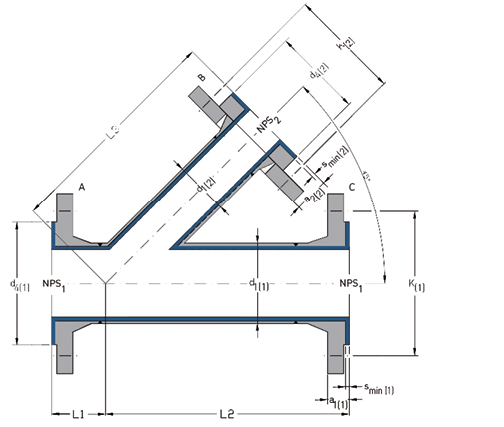
ANSI Flanged Lateral Tees 45° (Class 150)
The one-piece design with PFA or PP lining offers a low-resistance flow through the entire component by a streamlined geometry.
Materials:
- carbon steel
- stainless steel
Lining materials:
- PFA (virgin or conductive)
- PP
Flanges (reading order A-B-C):
- combinations of fixed flanges
- combinations of loose flanges
- combinations of fixed and loose flanges
Other pressure rating:
- Class 300
Special features:
- earthing stud/lug
- vent hole extension
- flange stopper
Optional extras:
- final painting
- non-destructive testing
NPS1
| NPS2
| L1
(mm) | L2 = L3(
mm) | d1(1)
(mm) | d4(1)
(mm) | K(1)
(mm) | smin (1)
(mm) | a1(1)
(mm) | a2(1)
(mm) | d1(2)
(mm) | d4(2)
(mm) | K(2)
(mm) | smin (2)
(mm) | a1(2)
(mm) | a2(2)
(mm) | No. of bolts x thread (UNC) | Wt.
(ca. | |
NPS1 | NPS2 | |||||||||||||||||
1“ | 1“ | 44 | 146 | 33.4 | 50.8 | 79.4 | 4.0 | 18.7 | 22.3 | 33.4 | 50.8 | 79.4 | 4.0 | 18.7 | 22.3 | 4 x ½“ | 4 x ½“ | 3.9 |
1½“ | 1½“ | 51 | 178 | 48.3 | 73.0 | 98.4 | 4.0 | 21.9 | 25.5 | 48.3 | 73.0 | 98.4 | 4.0 | 21.9 | 25.5 | 4 x ½“ | 4 x ½“ | 6.9 |
2“ | 1“ | 64 | 203 | 60.3 | 92.1 | 120.7 | 4.0 | 23.5 | 27.6 | 33.4 | 50.8 | 79.4 | 4.0 | 18.7 | 22.3 | 4 x ⅝“ | 4 x ½“ | 8.3 |
2“ | 1½“ | 64 | 203 | 60.3 | 92.1 | 120.7 | 4.0 | 23.5 | 27.6 | 48.3 | 73.0 | 98.4 | 4.0 | 21.9 | 25.5 | 4 x ⅝“ | 4 x ½“ | 9.3 |
2“ | 2“ | 64 | 203 | 60.3 | 92.1 | 120.7 | 4.0 | 23.5 | 27.6 | 60.3 | 92.1 | 120.7 | 4.0 | 23.5 | 27.6 | 4 x ⅝“ | 4 x ⅝“ | 10.5 |
3“ | 1“ | 76 | 254 | 88.9 | 127.0 | 152.4 | 4.0 | 28.3 | 33.4 | 33.4 | 50.8 | 79.4 | 4.0 | 18.7 | 22.3 | 4 x ⅝“ | 4 x ½“ | 15.5 |
3“ | 2“ | 76 | 254 | 88.9 | 127.0 | 152.4 | 4.0 | 28.3 | 33.4 | 60.3 | 92.1 | 120.7 | 4.0 | 23.5 | 27.6 | 4 x ⅝“ | 4 x ⅝“ | 17.7 |
3“ | 3“ | 76 | 254 | 88.9 | 127.0 | 152.4 | 4.0 | 28.3 | 33.4 | 88.9 | 127.0 | 152.4 | 4.0 | 28.3 | 33.4 | 4 x ⅝“ | 4 x ⅝“ | 21.3 |
4“ | 1“ | 76 | 305 | 114.3 | 157.2 | 190.5 | 4.0 | 28.3 | 33.9 | 33.4 | 50.8 | 79.4 | 4.0 | 18.7 | 22.3 | 8 x ⅝“ | 4 x ½“ | 21.8 |
4“ | 2“ | 76 | 305 | 114.3 | 157.2 | 190.5 | 4.0 | 28.3 | 33.9 | 60.3 | 92.1 | 120.7 | 4.0 | 23.5 | 27.6 | 8 x ⅝“ | 4 x ⅝“ | 24.2 |
4“ | 3“ | 76 | 305 | 114.3 | 157.2 | 190.5 | 4.0 | 28.3 | 33.9 | 88.9 | 127.0 | 152.4 | 4.0 | 28.3 | 33.4 | 8 x ⅝“ | 4 x ⅝“ | 28.0 |
4“ | 4“ | 76 | 305 | 114.3 | 157.2 | 190.5 | 4.0 | 28.3 | 33.9 | 114.3 | 157.2 | 190.5 | 4.0 | 28.3 | 33.9 | 8 x ⅝“ | 8 x ⅝“ | 31.1 |
NPS1 | NPS2 | Possible flanges | |||||||
fix-fix-fix | fix-fix-loose | fix-loose-fix | loose-fix-fix | fix-loose-loose | loose-loose-fix | loose-fix-Los | loose-loose-loose | ||
1“ | 1“ |
| - | - |
| - | - | - | - |
1½“ | 1½“ |
|
|
|
| - |
|
| - |
2“ | 1“ |
|
|
|
|
|
|
|
|
2“ | 1½“ |
|
|
|
| - |
|
| - |
2“ | 2“ |
| - | - |
| - | - | - | - |
3“ | 1“ |
|
|
|
|
|
|
|
|
3“ | 2“ |
|
|
|
|
|
|
|
|
3“ | 3“ |
| - | - |
| - | - | - | - |
4“ | 1“ |
|
|
|
|
|
|
|
|
4“ | 2“ |
|
|
|
|
|
|
|
|
4“ | 3“ |
|
|
|
| - |
|
| - |
4“ | 4“ |
| - | - |
| - | - | - | - |

Different nominal pipe sizes
and total lengths on request.
L = Total length
d1 = Outer diameter of the pipe
d4 = Raised face diameter
K = Bolt circle diameter
smin = Minimum flare thickness
a1 = Minimum length with fixed flange and smin
a2 = Minimum length with loose flangeand smin
Technical data valid for the pressure rating Class 150.
a1 and a2 depend on construction type and lining thickness.
| NPS | Lining thickness | Possible vacuum | |||
| standard | thick-walled | 23°C | 150°C | 200°C | |
| 1“ | |||||
| 1½“ | |||||
| 2“ | |||||
| 3“ | |||||
| 4“ | |||||
| = | full vacuum | |
| = | limited vacuu | |
| = | no vacuum | |
| Please refer to the next higher nominal pipe size if your nominal pipe size is not listed. | ||