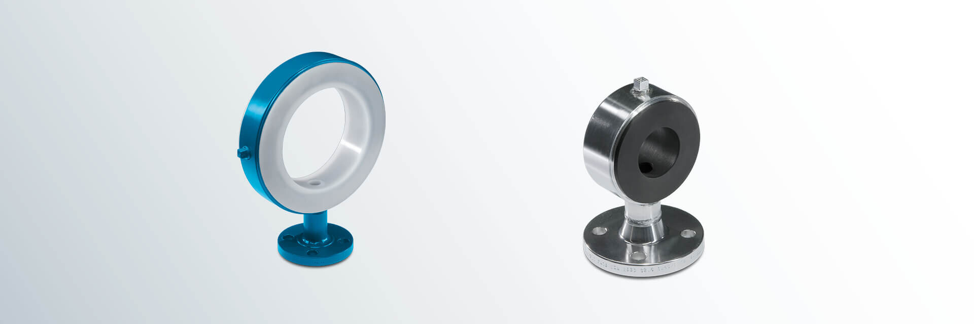
DIN Instrument Tees (PN 10)
Instrument Tees, also known as gauge connections, are the one-piece solution with PFA or PP lining for the connection to your measuring devices. In case of narrow space, also useable as short tee.
Materials:
- carbon steel
- stainless steel
Lining materials:
- PFA (virgin or conductive)
- PP
Other pressure levels:
- PN 16
- PN 25
- PN 40
Special features:
- earthing stud/lug
- vent hole extension
Optional extras:
- final painting
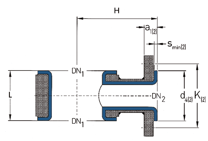
DN1
| DN2
| L
(mm) | H
(mm) | d4(2)
(mm) | K(2)
(mm) | smin (2)
(mm) | a1(2)
(mm) | No. of bolts x thread DN2 | Weights (ca. kg/piece)
|
25 | 15 | 50 | 90 | 45 | 65 | 4.0 | 20.0 | 4 x M12 | 2.0 |
25 | 20 | 50 | 90 | 58 | 75 | 4.0 | 22.0 | 4 x M12 | 2.4 |
25 | 25 | 50 | 90 | 68 | 85 | 4.0 | 22.0 | 4 x M12 | 2.6 |
32 | 15 | 50 | 100 | 45 | 65 | 4.0 | 20.0 | 4 x M12 | 2.3 |
32 | 20 | 50 | 100 | 58 | 75 | 4.0 | 22.0 | 4 x M12 | 2.8 |
32 | 25 | 50 | 100 | 68 | 85 | 4.0 | 22.0 | 4 x M12 | 3.0 |
40 | 15 | 50 | 110 | 45 | 65 | 4.0 | 20.0 | 4 x M12 | 2.7 |
40 | 20 | 50 | 110 | 58 | 75 | 4.0 | 22.0 | 4 x M12 | 3.1 |
40 | 25 | 50 | 110 | 68 | 85 | 4.0 | 22.0 | 4 x M12 | 3.3 |
40 | 40 | 75 | 110 | 88 | 110 | 4.0 | 22.0 | 4 x M16 | 5.4 |
50 | 15 | 50 | 115 | 45 | 65 | 4.0 | 20.0 | 4 x M12 | 3.2 |
50 | 20 | 50 | 115 | 58 | 75 | 4.0 | 22.0 | 4 x M12 | 3.7 |
50 | 25 | 50 | 115 | 68 | 85 | 4.0 | 22.0 | 4 x M12 | 3.9 |
50 | 40 | 75 | 115 | 88 | 110 | 4.0 | 22.0 | 4 x M16 | 6.3 |
50 | 50 | 90 | 115 | 102 | 125 | 4.0 | 22.0 | 4 x M16 | 7.6 |
65 | 15 | 50 | 125 | 45 | 65 | 4.0 | 20.0 | 4 x M12 | 4.0 |
65 | 20 | 50 | 125 | 58 | 75 | 4.0 | 22.0 | 4 x M12 | 4.4 |
65 | 25 | 50 | 125 | 68 | 85 | 4.0 | 22.0 | 4 x M12 | 4.6 |
65 | 40 | 75 | 125 | 88 | 110 | 4.0 | 22.0 | 4 x M16 | 8.3 |
65 | 50 | 90 | 125 | 102 | 125 | 4.0 | 22.0 | 4 x M16 | 9.1 |
80 | 15 | 50 | 135 | 45 | 65 | 4.0 | 20.0 | 4 x M12 | 4.5 |
80 | 20 | 50 | 135 | 58 | 75 | 4.0 | 22.0 | 4 x M12 | 5.0 |
80 | 25 | 50 | 135 | 68 | 85 | 4.0 | 22.0 | 4 x M12 | 5.2 |
80 | 40 | 75 | 135 | 88 | 110 | 4.0 | 22.0 | 4 x M16 | 8.3 |
80 | 50 | 90 | 135 | 102 | 125 | 4.0 | 22.0 | 4 x M16 | 11.2 |
100 | 15 | 50 | 150 | 45 | 65 | 4.0 | 20.0 | 4 x M12 | 5.0 |
100 | 20 | 50 | 150 | 58 | 75 | 4.0 | 22.0 | 4 x M12 | 5.4 |
100 | 25 | 50 | 150 | 68 | 85 | 4.0 | 22.0 | 4 x M12 | 5.7 |
100 | 40 | 75 | 150 | 88 | 110 | 4.0 | 22.0 | 4 x M16 | 9.1 |
100 | 50 | 90 | 150 | 102 | 125 | 4.0 | 22.0 | 4 x M16 | 12.2 |
125 | 15 | 50 | 160 | 45 | 65 | 4.0 | 20.0 | 4 x M12 | 6.2 |
125 | 20 | 50 | 160 | 58 | 75 | 4.0 | 22.0 | 4 x M12 | 6.7 |
125 | 25 | 50 | 160 | 68 | 85 | 4.0 | 22.0 | 4 x M12 | 6.9 |
125 | 40 | 75 | 160 | 88 | 110 | 4.0 | 22.0 | 4 x M16 | 11.0 |
125 | 50 | 90 | 160 | 102 | 125 | 4.0 | 22.0 | 4 x M16 | 13.3 |
150 | 15 | 50 | 180 | 45 | 65 | 4.0 | 20.0 | 4 x M12 | 6.9 |
150 | 20 | 50 | 180 | 58 | 75 | 4.0 | 22.0 | 4 x M12 | 7.4 |
150 | 25 | 50 | 180 | 68 | 85 | 4.0 | 22.0 | 4 x M12 | 7.6 |
150 | 40 | 75 | 180 | 88 | 110 | 4.0 | 22.0 | 4 x M16 | 12.1 |
150 | 50 | 90 | 180 | 102 | 125 | 4.0 | 22.0 | 4 x M16 | 14.7 |
200 | 15 | 50 | 210 | 45 | 65 | 4.0 | 20.0 | 4 x M12 | 9.5 |
200 | 20 | 50 | 210 | 58 | 75 | 4.0 | 22.0 | 4 x M12 | 9.9 |
200 | 25 | 50 | 210 | 68 | 85 | 4.0 | 22.0 | 4 x M12 | 10.1 |
200 | 40 | 75 | 210 | 88 | 110 | 4.0 | 22.0 | 4 x M16 | 16.1 |
200 | 50 | 90 | 210 | 102 | 125 | 4.0 | 22.0 | 4 x M16 | 19.6 |
250 | 25 | 50 | 240 | 68 | 85 | 4.0 | 22.0 | 4 x M12 | 13.7 |
250 | 40 | 75 | 240 | 88 | 110 | 4.0 | 22.0 | 4 x M16 | 21.7 |
250 | 50 | 90 | 240 | 102 | 125 | 4.0 | 22.0 | 4 x M16 | 26.4 |
300 | 25 | 90 | 340 | 68 | 85 | 4.0 | 22.0 | 4 x M12 | 27.5 |
300 | 40 | 110 | 340 | 88 | 110 | 4.0 | 22.0 | 4 x M16 | 34.8 |
300 | 50 | 120 | 340 | 102 | 125 | 4.0 | 22.0 | 4 x M16 | 38.5 |
350 | 25 | 90 | 375 | 68 | 85 | 4.0 | 22.0 | 4 x M12 | 43.2 |
350 | 40 | 110 | 375 | 88 | 110 | 4.0 | 22.0 | 4 x M16 | 54.2 |
350 | 50 | 120 | 375 | 102 | 125 | 4.0 | 22.0 | 4 x M16 | 59.7 |
400 | 25 | 90 | 390 | 68 | 85 | 4.0 | 22.0 | 4 x M12 | 48.3 |
400 | 40 | 110 | 390 | 88 | 110 | 4.0 | 22.0 | 4 x M16 | 60.5 |
400 | 50 | 120 | 390 | 102 | 125 | 4.0 | 22.0 | 4 x M16 | 66.6 |
450 | 25 | 90 | 425 | 68 | 85 | 4.0 | 22.0 | 4 x M12 | 51.1 |
450 | 40 | 110 | 425 | 88 | 110 | 4.0 | 22.0 | 4 x M16 | 64.0 |
450 | 50 | 120 | 425 | 102 | 125 | 4.0 | 22.0 | 4 x M16 | 70.6 |
500 | 25 | 90 | 450 | 68 | 85 | 4.0 | 22.0 | 4 x M12 | 66.5 |
500 | 40 | 110 | 450 | 88 | 110 | 4.0 | 22.0 | 4 x M16 | 83.1 |
500 | 50 | 120 | 450 | 102 | 125 | 4.0 | 22.0 | 4 x M16 | 91.5 |
Different nominal pipe sizes, total lengths and
other construction types on request.
L = Total length
H = Overall height
d4 = Raised face diameter
K = Bolt circle diameter
smin = Minimum flare thickness
a1 = Minimum length with fixed flange (Type 11)
and smin
Technical data valid for the pressure level PN 10.
a1 depends on construction type and lining thickness.
| DN | Lining thickness | Possible vacuum | |||
| standard | thick-walled | 23°C | 150°C | 200°C | |
| 25 | |||||
| 40 | |||||
| 50 | |||||
| 80 | |||||
| 100 | |||||
| 150 | |||||
| 200 | |||||
| 250 | |||||
| 300 | |||||
| = | full vacuum | |
| = | limited vacuum | |
| = | no vacuum | |
| Please refer to the next higher nominal pipe size if your nominal pipe size is not listed. | ||