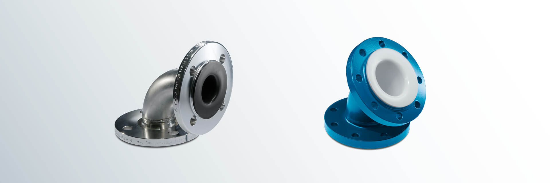
DIN Flanged Elbows 45°/90° (PN 10)
The BAUM manufacturing technology with paste-extruded PTFE liner assures an optimum flow and an exact fitting of the liner in the elbow segment.
Materials:
- carbon steel
- stainless steel
Lining materials:
- PTFE (virgin or conductive)
- PP (up to nominal pipe size DN 300)
Flanges according to EN 1092-1:
- fix-loose
- fix-fix
- loose-loose
Other pressure levels:
- PN 16
- PN 25
- PN 40
Special features:
- earthing stud/lug
- vent hole extension
- flange stopper
Optional extras:
- final painting
- non-destructive testing
DN | L (mm) | d1 (mm) | d4 (mm) | K (mm) | smin (mm) | a1 (mm) | a2 (mm) | No. of bolts
x thread | Weights | ||||
45° | 90° | 45° | 90° | 45° | 90° | ||||||||
Form C | Form A | Form D | Form B | Form | Form A | ||||||||
Type 3 (standard sizes) | Type 5 (special sizes) | (ca. kg/pc.) | (ca. kg/pc.) | ||||||||||
15 | use Form D | use Form B | 60 | 85 | 26.9 | 45 | 65 | 3.0 | 19.0 | 29.0 | 4 x M12 | 1.8 | 1.9 |
20 | 65 | 95 | 26.9 | 58 | 75 | 3.0 | 21.0 | 33.0 | 4 x M12 | 2.5 | 2.6 | ||
25 | 70 | 110 | 33.7 | 68 | 85 | 3.0 | 21.0 | 33.0 | 4 x M12 | 3.1 | 3.2 | ||
32 | 80 | 130 | 42.4 | 78 | 100 | 3.0 | 21.0 | 35.0 | 4 x M16 | 4.5 | 4.7 | ||
40 | 90 | 150 | 48.3 | 88 | 110 | 4.0 | 22.0 | 36.0 | 4 x M16 | 5.4 | 5.7 | ||
50 | 80 | 120 | 105 | 180 | 60.3 | 102 | 125 | 4.0 | 22.0 | 40.0 | 4 x M16 | 6.6 | 7.0 |
65 | 85 | 140 | 120 | 220 | 76.1 | 122 | 145 | 4.0 | 22.0 | 40.0 | 8 x M16 | 8.3 | 8.9 |
80 | 100 | 165 | 135 | 255 | 88.9 | 138 | 160 | 4.0 | 24.0 | 40.0 | 8 x M16 | 10.4 | 11.5 |
100 | 115 | 205 | 165 | 320 | 114.3 | 158 | 180 | 4.5 | 24.5 | 44.5 | 8 x M16 | 13.1 | 16.1 |
125 | 135 | 245 | 190 | 385 | 139.7 | 188 | 210 | 4.5 | 26.5 | 44.5 | 8 x M16 | 18.2 | 21.0 |
150 | 150 | 285 | 215 | 440 | 168.3 | 212 | 240 | 5.0 | 27.0 | 49.0 | 8 x M20 | 23.9 | 28.3 |
200 | 190 | 365 | 270 | 570 | 219.1 | 268 | 295 | 6.0 | 30.0 | 50.0 | 8 x M20 | 38.4 | 48.2 |
250 | 225 | 450 | 335 | 710 | 273.0 | 320 | 350 | 6.0 | 32.0 | 54.0 | 12 x M20 | 53.9 | 68.8 |
300 | 260 | 525 | 385 | 830 | 323.9 | 370 | 400 | 6.0 | 32.0 | 54.0 | 12 x M20 | 69.2 | 121.6 |
350 | 290 | 600 | 430 | 910 | 355.6 | 430 | 460 | 7.0 | 33.0 | 59.0 | 16 x M20 | 93.2 | 168.4 |
400 | 325 | 680 | 480 | 1030 | 406.4 | 482 | 515 | 7.5 | 33.5 | 63.5 | 16 x M24 | 122.3 | 225.5 |
450 | 355 | 705 | 575 | 1140 | 457.0 | 532 | 565 | 5.0 | 33.0 | 65.0 | 20 x M24 | 139.9 | 256.2 |
500 | 390 | 830 | 585 | 1300 | 508.0 | 585 | 620 | 5.0 | 33.0 | 69.0 | 20 x M24 | 170.2 | 404.0 |
Nominal pipe sizes over DN 500 up to DN 1000
and other construction types on request.
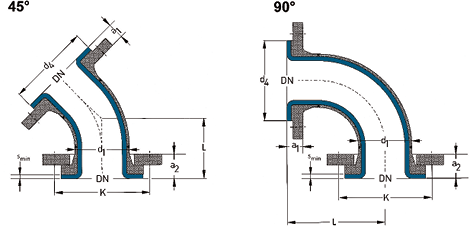
L = Total length
d1 = Outer diameter of the elbow
d4 = Raised face diameter
K = Bolt circle diameter
smin = Minimum flare thickness
a1 = Minimum length with fixed flange (Type 11) and smin
a2 = Minimum length with loose flange (Types 04/34) and smin
Technical data valid for the pressure level PN 10.
a1 and a2 depend on construction type and lining thickness.
Types of Flanged Elbows:
- from nominal pipe size DN 300 as two-part component
- nominal pipe size DN 450 Form B as three-part component
- from nominal pipe size DN 500 as three-part component
| DN | Lining thickness | Possible vacuum | |||
| standard | thick-walled | 23°C | 150°C | 200°C | |
| 25 | |||||
| 40 | |||||
| 50 | |||||
| 80 | |||||
| 100 | |||||
| 150 | |||||
| 200 | |||||
| 250 | |||||
| 300 | |||||
| = | full vacuum | |
| = | limited vacuum | |
| = | no vacuum | |
| Please refer to the next higher nominal pipe size if your nominal pipe size is not listed. | ||