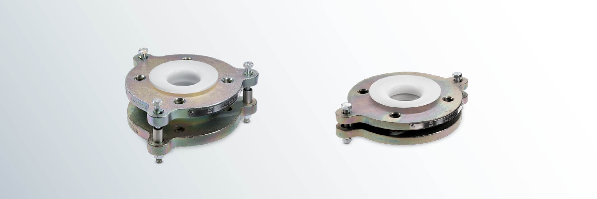
DIN PTFE Expansion Joints, 1 convolute (PN 10) – new design
Our PTFE Expansion Joints are highly flexible and provide compensation of vibrations and heat-induced expansion in your production line. PTFE Expansion Joints with 1 convolute allow high working pressures.
Designs:
- up to nominal pipe size DN 100 with two ears
- from nominal pipe size DN 125 with three ears
- up to nominal pipe size DN 65 with threaded holes
- from nominal pipe size DN 80 with through holes
Flange materials:
- carbon steel
- stainless steel
Lining material:
- PTFE (virgin or conductive)
Flanges:
- loose-loose
Other pressure levels:
- on request
Special features:
- limit bolts/hole extensions
- earthing stud/lug
Optional extras:
- final painting
DN
| L
(mm) | Stroke ± (mm) | Lateral offset (mm) | Angular offset
max. (°) | d4
(mm) | K
(mm) | smin
(mm) | a2
(mm) | No. of bolts x thread | Weights
(ca. kg/pc.) |
15 | 40 | 5 | 2 | 2 | 45 | 65 | 3.0 | 13.0 | 4 x M12 | 1.3 |
20 | 40 | 5 | 2 | 2 | 58 | 75 | 3.0 | 13.0 | 4 x M12 | 1.6 |
25 | 40 | 5 | 2 | 2 | 68 | 85 | 3.0 | 13.0 | 4 x M12 | 1.9 |
32 | 40 | 5 | 2 | 2 | 78 | 100 | 3.0 | 13.0 | 4 x M16 | 2.7 |
40 | 40 | 5 | 2 | 2 | 88 | 110 | 3.0 | 13.0 | 4 x M16 | 3.1 |
50 | 48 | 6 | 2 | 2 | 102 | 125 | 4.0 | 16.0 | 4 x M16 | 4.4 |
65 | 54 | 7 | 3 | 3 | 122 | 145 | 4.0 | 16.0 | 8 x M16 | 5.2 |
80 | 60 | 7 | 3 | 3 | 138 | 160 | 4.0 | 16.0 | 8 x M16 | 6.2 |
100 | 64 | 7 | 3 | 4 | 158 | 180 | 5.0 | 20.0 | 8 x M16 | 8.4 |
125 | 70 | 7 | 4 | 4 | 188 | 210 | 4.5 | 19.5 | 8 x M16 | 11.1 |
150 | 75 | 10 | 4 | 4 | 212 | 240 | 5.0 | 23.0 | 8 x M20 | 15.9 |
200 | 85 | 10 | 4 | 3 | 268 | 295 | 5.0 | 25.0 | 8 x M20 | 25.4 |
250 | 93 | 10 | 5 | 3 | 320 | 350 | 7.5 | 29.5 | 12 x M20 | 32.1 |
300 | 100 | 12 | 5 | 3 | 370 | 400 | 6.0 | 31.0 | 12 x M20 | 52.8 |
350 | 103 | 12 | 5 | 2 | 430 | 460 | 7.5 | 37.5 | 16 x M20 | 72.2 |
400 | 103 | 12 | 5 | 2 | 482 | 515 | 7.5 | 37.5 | 16 x M24 | 83.2 |
500 | 103 | 12 | 5 | 2 | 585 | 620 | 8.0 | 38.0 | 20 x M24 | 93.7 |
DN | Overpressure resistance (105 Pa) at | Vacuum resistance (105 Pa) at | ||||||
23° C | 100° C | 150° C | 200° C | 23° C | 100° C | 150° C | 200° C | |
15 | 10.0 | 10.0 | 8.3 | 5.8 | -1.00 | -1.00 | -1.00 | -1.00 |
20 | 10.0 | 10.0 | 8.3 | 5.8 | -1.00 | -1.00 | -1.00 | -1.00 |
25 | 10.0 | 10.0 | 8.3 | 5.8 | -1.00 | -1.00 | -1.00 | -1.00 |
32 | 10.0 | 10.0 | 8.3 | 5.8 | -1.00 | -1.00 | -1.00 | -1.00 |
40 | 10.0 | 10.0 | 8.3 | 5.8 | -1.00 | -1.00 | -1.00 | -1.00 |
50 | 10.0 | 10.0 | 8.3 | 5.8 | -1.00 | -1.00 | -1.00 | -1.00 |
65 | 10.0 | 10.0 | 8.3 | 5.8 | -1.00 | -1.00 | -1.00 | -1.00 |
80 | 10.0 | 10.0 | 8.3 | 5.8 | -1.00 | -1.00 | -1.00 | -1.00 |
100 | 10.0 | 10.0 | 8.3 | 5.8 | -1.00 | -1.00 | -1.00 | -1.00 |
125 | 10.0 | 9.2 | 6.9 | 4.8 | -1.00 | -1.00 | -1.00 | -0.80 |
150 | 10.0 | 9.2 | 6.9 | 4.8 | -1.00 | -1.00 | -1.00 | -0.80 |
200 | 10.0 | 7.7 | 5.8 | 4.0 | -1.00 | -1.00 | -1.00 | -0.70 |
250 | 10.0 | 6.0 | 4.5 | 3.2 | -1.00 | -1.00 | -0.80 | -0.55 |
300 | 10.0 | 6.0 | 4.5 | 3.2 | -1.00 | -1.00 | -0.65 | -0.45 |
Different nominal pipe sizes
and total lengths on request.
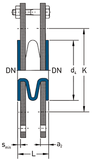
L = Total length
d4 = Raised face diameter
K = Bolt circle diameter
smin = Minimum flare thickness
a2 = Minimum length with loose flange and smin
Technical data valid for the pressure level PN 10.
a2 depends on construction type and lining thickness.
The overpressure resistance is only valid at neutral position of the PTFE Expansion Joint with limit bolts in place. The types of travel stroke, lateral offset and angular offset are maximum allowable movements in only one direction. For superpositioned movement the single types of travel need to be limited. The figures stated are average and apply to room temperature.